Pressure Testing OpenROV Housings
As part of our ongoing OpenROV redesign effort, we destructively pressure tested the main OpenROV pressure tube (which contains the camera, computer, and other electronics) and the battery tubes to determine at what pressure they would fail. The video below shows the main pressure tube being tested to catastrophic failure in the pressure tank at the Southwest Fisheries Science Center Acoustics Lab.
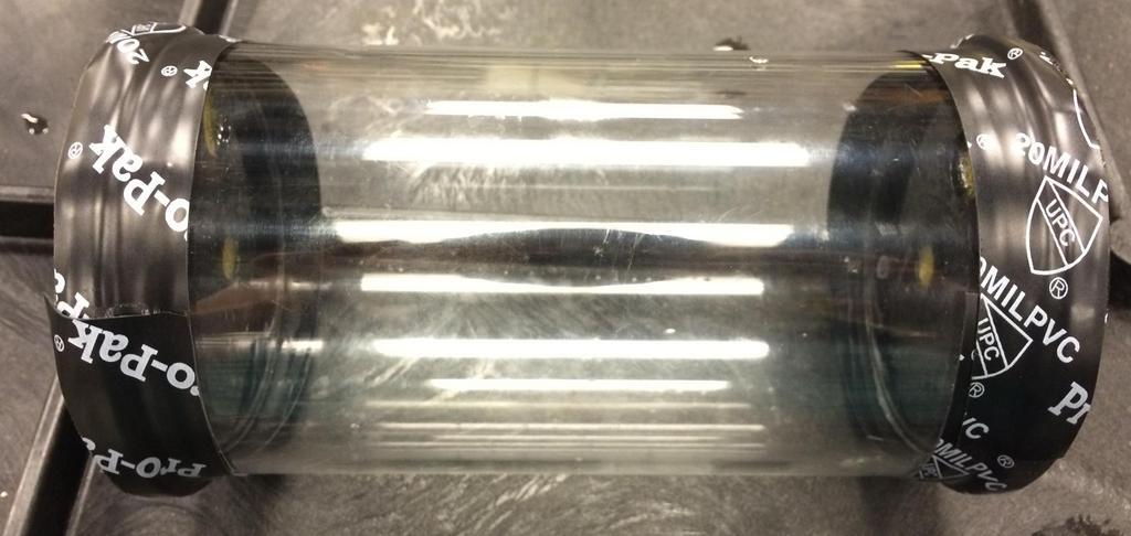
The pressure tubes are made of 1/8-inch thick acrylic, with endcaps made of pieces of lasercut acrylic glued together in a stack to hold the o-ring. This is a very low-cost solution for an underwater housing. However, acrylic is brittle and will shatter under high enough compressive forces (as seen in the above video), which is an undesirable trait for an underwater robot housing. A better design strategy would be to design the housing to leak at a high pressure and install a leak detector inside, which could trigger an emergency ascent in hopes of saving the system. We are redesigning the housing to use materials with a higher elasticity than acrylic, which should achieve the goal of leaking before catastrophic failure.
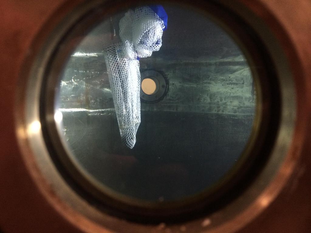
Battery Tube Testing Results The battery tubes were placed in the tank with the epoxy-sealed end downward, and the o-ring seal at the top. The battery tubes leaked early on in the test. The leak was first noticed at a pressure of around 19.9 psi, which corresponds to a depth in seawater of about 45 feet, but probably started at a lower pressure since there were about 1.5 centimeters of water in the bottom of the tube when the leak was first observed.
Measured Starting Pressure (Relative): 0 dbar
Pressure at which water observed in tube #1 (Relative): 3.6 dbar (5.2 psi)
Pressure at which water observed in tube #1 (Absolute): 13.7 dbar (19.9 psi)
Failure Depth (Seawater): 45 feet
During the test, bubbling was observed from the bottom of the tube where the battery tubes were sealed with epoxy, and the tubes appeared to fill only from the bottom. No bubbling was observed from the top of the tube where the o-ring seal was located. This was likely due to assembly error in epoxy potting the aft endcaps. The epoxy seal appeared to be full of bubbles, which could lead to holes in the seal, and had not completely hardened, suggesting assembly errors in both mixing and applying the epoxy. We will fix the seal on the endcaps and test again to try to determine a more accurate failure mode.
The test was run until the tubes were full of water to see if the seal would completely break or if it would continue to slowly leak. The tubes continued to leak until they were full, at which point the test was ended. The final pressure achieved was around 350 psi, or a depth of around 847 feet in seawater.
Main Tube Testing Results The main tube leaked as soon as it was put into the tank. We suspect that this was due to manufacturing error in the endcaps, as the lens on our laser cutter may not be properly calibrated and may have cut the endcaps slightly small. Also, the tube may have been slightly warped, since the pieces of the endcaps appeared to be concentric and yet the tube was not evenly sealed along the perimeter of the endcap. Regardless of the cause, the seal was clearly not sufficient to any depth. To counteract this, we lubricated the o-rings with barium grease and wrapped the seals with self-adhesive rubber electrical tape, then wrapped the electrical tape with 20-mil PVC tape. This in situ solution likely contributed to the implosion of the tube, as it prevented any leak from occurring in the o-ring. We will test again with properly-manufactured endcaps to see if the housings fail due to leaking before implosion.
Measured Starting Pressure (Relative): 0 dbar
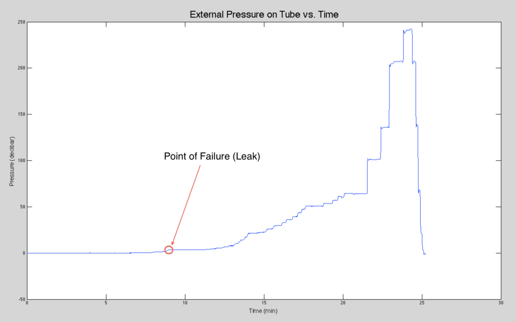
Measured Failure Pressure (Relative): 76.4 dbar (111 psi)
Failure Pressure (Absolute): 86.9 dbar (126 psi)
Failure Depth (Seawater): 283 feet (86.3 m)
The measured failure pressure corresponds to a failure pressure of 126 psi when correcting for a starting pressure at sealevel (14.7 psi). This is a failure depth of approximately 283 feet in seawater.
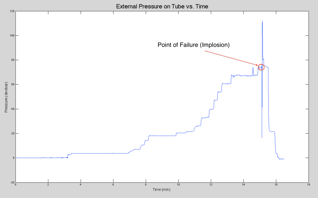
The graph above shows the internal tank pressure (which is the external pressure on the tube) in decibars versus time in minutes. The pressure was increased in increments of 5 psi at first, then in increments of 10 psi later on in the test. The point at which the tube imploded is marked by a red circle. This is followed by a significant measured drop in pressure, which is caused by the volume of the tube being filled by the water, and a subsequent spike in pressure which we speculate was caused by the tank overcompensating for the pressure drop. The pressure then evens out, at which point we turned off the system and let the pressure bleed out.
Failure Analysis
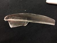
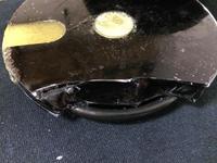
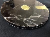
Prior to the test, the theoretical buckling pressure of the tube was computed using Windenburg and Trilling’s buckling equation. The theoretical critical pressure for buckling computed was 122 psi. The experimental failure pressure recorded was 126 psi. This corresponds to a plastic knockdown factor of 0.968 (PKD = theoretical pressure / experimental pressure).
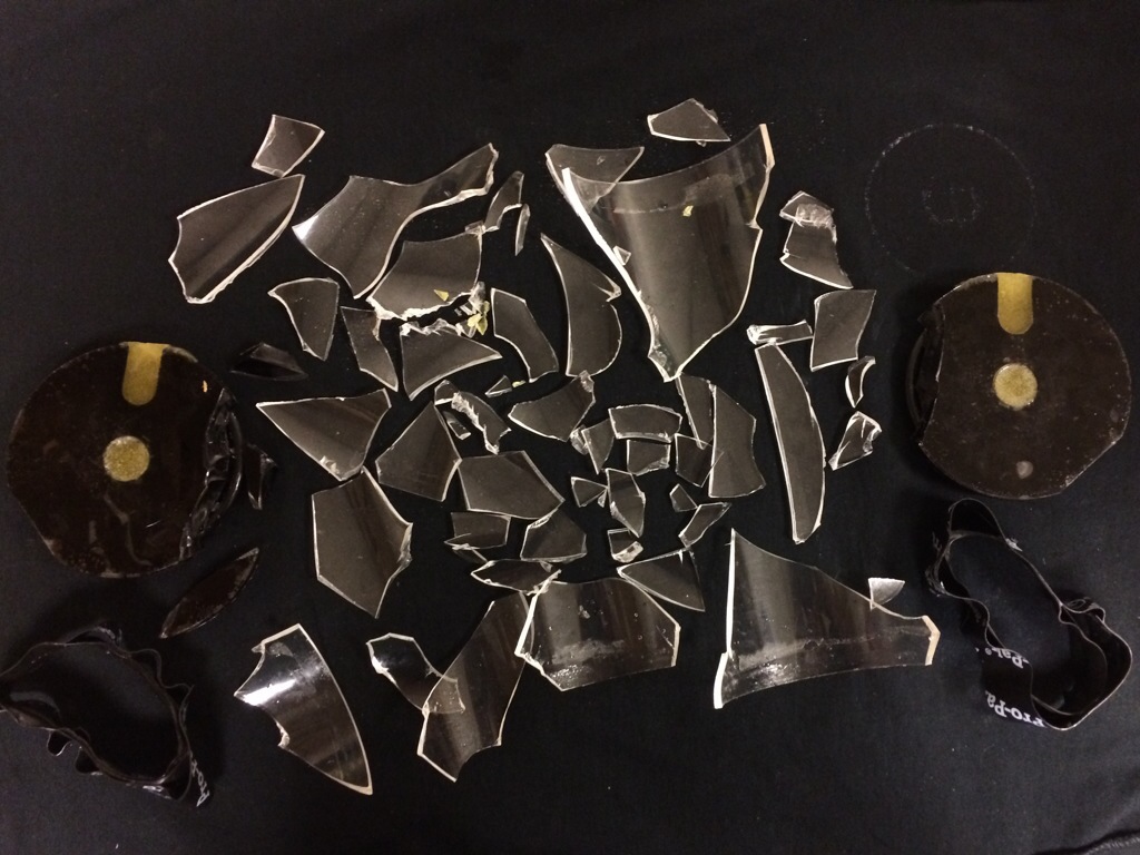
The acrylic tube walls buckled first. The endcaps were left mostly intact, but each endcap had a small piece break off the side (pictured above). The points where the endcaps failed could have been due to bubbles trapped in the glue between the plates of the endcap.
Our next step in the redesign is to rebuild the tube with different materials to see if they produce different failure modes. Ultimately, we would like to produce a design that leaks or warps before implosion, and include a leak detector that will trigger an emergency ascent in order to protect the internal electronics and sensors.
